Baremetal USB Project
This project is on GitHub: link
In this project, the signals will be transmitted via USB. With this improvement, we can finally hear the signals without experiencing jitters and pops. Let’s get started!
table of contents
General Concepts
“Take a look at the main(). This approach is known as a super-loop-based system, where the three functions, namely user_input_control(), audio_task(feed), and tud_task(), are called infinitely. Additionally, these repetitively called functions should probably have while loops, in which the CPU waits for some tasks, like DMA interrupts, to be fired. So, this approach involves while loops inside while loops, which can be very inefficient. However, it is still relatively simple to understand. Nevertheless, adding more complexity to this project is not recommended. Debugging bare metal can be very challenging, and the code can easily become spaghetti-like.
  /* Initialize all configured peripherals */
  MX_GPIO_Init();
  MX_DMA_Init();
  MX_I2C1_Init();
  MX_I2S3_Init();
  MX_I2S2_Init();
  MX_CRC_Init();
  MX_USB_OTG_FS_PCD_Init();
  MX_PDM2PCM_Init();
  MX_SPI1_Init();
  MX_TIM4_Init();
  MX_USART2_UART_Init();
  /* USER CODE BEGIN 2 */

    tud_init(BOARD_TUD_RHPORT);

    if (board_init_after_tusb) {
        board_init_after_tusb();
    }

    sampFreq = sampleRatesList[0];
    clkValid = 1;

    /* enable DMA from Mic to rxBuff */
    enable_mic_dma();

    /* activate CODEC and enable DMA from pcmBuff */
    setup_codec();

  /* USER CODE END 2 */

  /* Infinite loop */
  /* USER CODE BEGIN WHILE */
  print_welcome_message();
  print_menu_message();
  while (1)
  {
    /* USER CODE END WHILE */

    /* USER CODE BEGIN 3 */
      user_input_control();
      audio_task(feed);
      tud_task();
  }
  /* USER CODE END 3 */
The user_input_control() function checks if the user has sent a character using UART, otherwise, it does nothing, and the main while loop continues.
If the user sends a character, the loop retrieves it from uart_rx_buff and updates the uart_dma_rx_state to DMA_READY to receive another character. It also calls clear_reset_terminal() to reset the current menu.
Following that, the function prints several messages and/or changes mode flags based on the user input. Additionally, there is another menu called mode_menu, which is another extensive switch.
The mode_menu changes only the mode_list, a simple struct containing several modes as uint8_t. It modifies them using XOR, an efficient way of toggling between 0 and 1. The mode_list variable will be read by various functions to enable/disable specific features along the way.
void user_input_control() {
    if (uart_dma_rx_state == RX_RECEIVED) {
        uint8_t user_input = uart_rx_buff[0];
        uart_dma_rx_state = DMA_READY;

        clear_reset_terminal();

        switch (user_input) {
            case '1':
                print_serial(mode_message);
                mode_select_loop();
                request_input();
                break;
            case '2':
                mode_list.debug_mode ^= 1;
                mode_list.debug_mode ? (print_serial("\n\rDEBUG mode enabled\n\r")) : (print_serial(
                        "\n\rDEBUG mode disabled\n\r"));
                print_serial(return_main_menu_message);
                request_input();
                break;
            case '9':
                print_serial(details_message);
                request_input();
                break;
            case '0':
                print_serial(menu_message);
                request_input();
                break;
            default:
                print_serial(invalid_input_error_message);
                print_serial(menu_message);
                request_input();
                break;
        }

        change_led_states();
        change_feed();

    }
}
void mode_select_loop() {
    uint8_t selection_finished = 0;
    while (!selection_finished) {
        request_input();
        while (uart_dma_rx_state != RX_RECEIVED) { __NOP(); } // todo: this busy wait is not a good idea
        uart_dma_rx_state = DMA_READY;
        uint8_t mode_select_input = uart_rx_buff[0];
        switch (mode_select_input) {
            case '1':
                mode_list.mic_in ^= 1;  // using ^= (xor) toggles the previous value, very easy to add
                mode_list.signal_in = 0;
                break;
            case '2':
                mode_list.signal_in ^= 1;
                mode_list.mic_in = 0;
                break;
            case '3':
                mode_list.usb_out ^= 1;
                break;
            case '4':
                mode_list.dac_out ^= 1;
                break;
            case '5':
                mode_list.filter_apply ^= 1;
                break;
            case '0':
                selection_finished = 1;
                break;
            default:
                print_serial("\n\r mode not understood. Try again\n\r");
                break;
        }
        /* show the user which mod is selected by simply printing the rx_value */
        char mode_select_char = mode_select_input + '\0';
        print_serial(&mode_select_char);
    }
    clear_reset_terminal();
    print_serial(menu_message);
}
void clear_reset_terminal() {
    print_serial(init_code);
    print_serial(clear_code);
}
At the end of user_input_control(), two functions are called to modify “feed” and “led_states”. The ‘feed’ represents the signal input source, which can be the generated cosine signal, microphone signal, or nothing. Additionally, ‘led_states’ control the timer’s PWM output, directly linked to the on-board LEDs.
void change_feed() {
    if (mode_list.mic_in) {
        feed = &feed_mic_data;
    } else if (mode_list.signal_in) {
        feed = &feed_signal_data;
    } else {
        feed = &feed_nothing;
    }
}

void change_led_states() {
    /* control LEDs after possible mod selection */
    /*
    * TIM4 CHANNELS FOR LED'S
    * 0 -> green
    * 1 -> orange
    * 2 -> red
    * 3 -> blue
    */
    tim_channel_control(3, mode_list.signal_in);
    tim_channel_control(2, mode_list.mic_in);
    tim_channel_control(1, mode_list.filter_apply);
    tim_channel_control(0, (mode_list.usb_out || mode_list.dac_out));
}
DMA Transfers
There are two DMA instances: one for UART communication and another for I2S communication with the microphone.
The UART DMA is utilized during the console application, where the flag uart_dma_rx_state is raised to RX_RECEIVED when a character is received from the console. Subsequently, when the user_input_control() function is invoked in the main loop, this character can be processed, and actions can be taken accordingly. Additionally, for sending the mode menu, welcome message, and generally providing feedback to the user, we also transmit data to the console. This transmission is controlled by uart_dma_tx_state.
The callbacks can be seen here:
void HAL_UART_RxCpltCallback(UART_HandleTypeDef *huart) {
    if (huart->Instance == USART2) {
        uart_dma_rx_state = RX_RECEIVED;
    }
}

void HAL_UART_TxCpltCallback(UART_HandleTypeDef *huart) {
    if (huart->Instance == USART2) {
        uart_dma_tx_state = DMA_READY;
    }
}
The functions print_serial() and request_input() are also protected with a guard condition while (uart_dma_tx_state != DMA_READY) { __NOP(); } to ensure the stability of DMA operations. During TX/RX operations, receiving data is not allowed. You can experiment by removing this guard, but be aware that this is likely to result in non-functional behavior.
void print_serial(const char* msg) {
    while (uart_dma_tx_state != DMA_READY) { __NOP(); }
    uart_dma_tx_state = DMA_BUSY;

    clear_buffer(uart_tx_buff, TX_SIZE);
    strcpy((char *) uart_tx_buff, msg);
    HAL_UART_Transmit_DMA(&huart2, uart_tx_buff, strlen(msg));
}

void request_input() {
    while (uart_dma_tx_state != DMA_READY) { __NOP(); }
    clear_buffer(uart_rx_buff, RX_SIZE);
    print_serial("\n\r> ");
    HAL_UART_Receive_DMA(&huart2, uart_rx_buff, 1);
}
WARNING
Be careful using DMA for RX and TX. Accessing the buffers during TX and RX operations is prohibited. Only one operation is allowed at a time, similar to the use of mutexes. For a quirky yet insightful explanation using a rubber chicken, refer to [1].
USB Transfers
Let’s discuss the signal generation and processing part. As mentioned above, the second DMA is dedicated to I2S communication. We are retrieving data from the integrated CMOS microphone, MP45DT02.
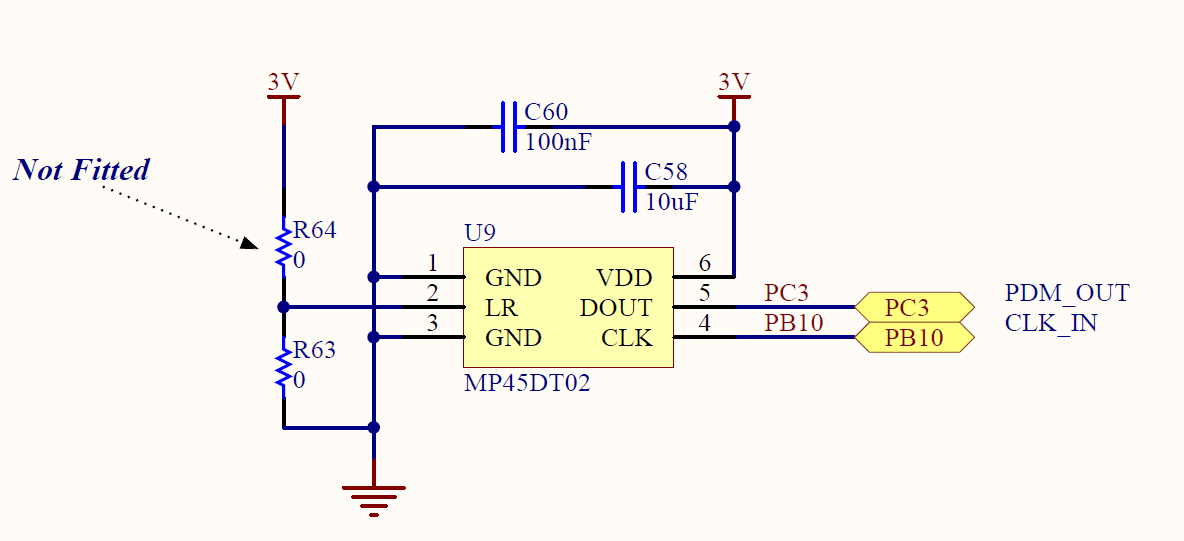
In this configuration, the LR pin is connected to 3V, which implies, as per [2], that the data is valid only when the serial CLK is high.
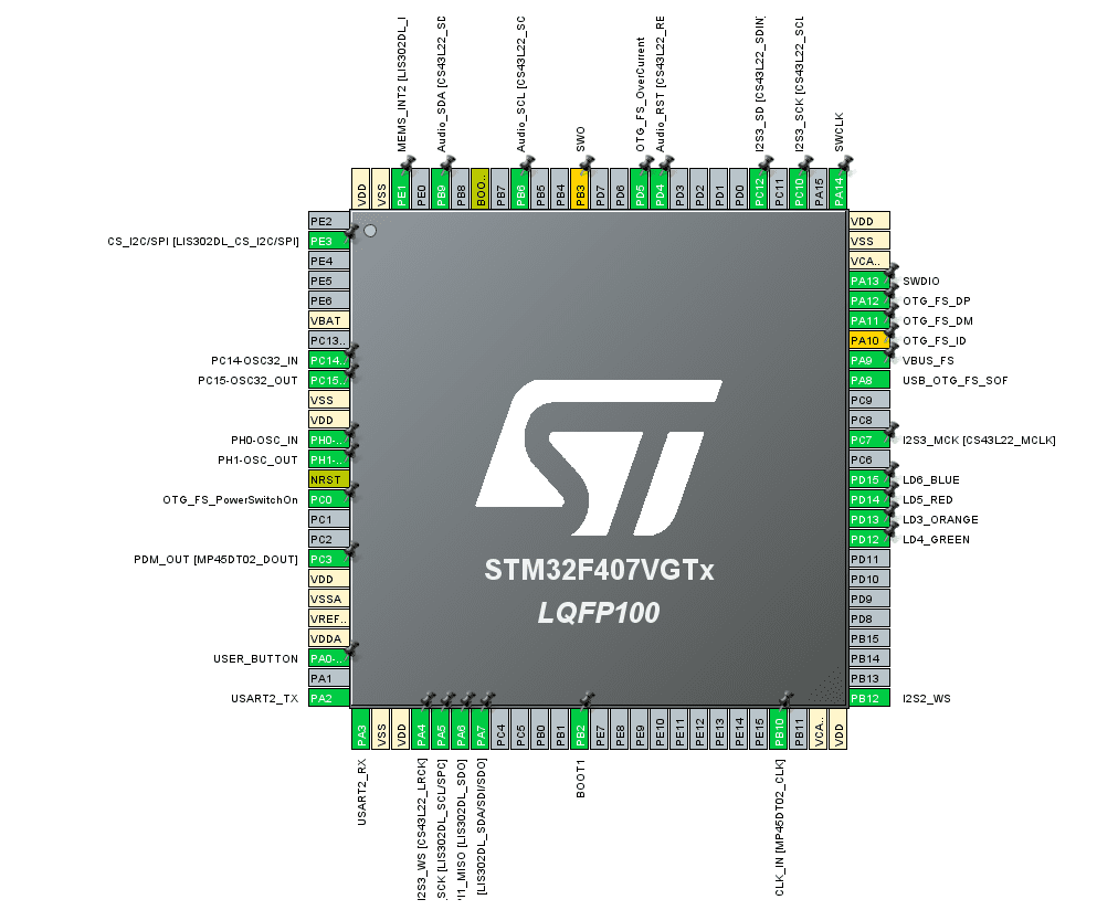
PB10 requires a serial master clock, and PC3 outputs the data. The applied settings are:
I2S
- Transmission Mode: Mode Master Receive
- Standard: LSB first (Right Justified)
- Data and Frame format: (16 bits Data on 16 bits Frame)
- Selected Audio Frequency: 192 kHz
- Clock Polarity: High
Do not forget to activate DMA for I2S2:
void HAL_I2S_RxHalfCpltCallback(I2S_HandleTypeDef *hi2s) {
    if (hi2s->Instance == SPI2) {
        rx_state = FIRST_HALF_READY;
    }
}

void HAL_I2S_RxCpltCallback(I2S_HandleTypeDef *hi2s) {
    if (hi2s->Instance == SPI2) {
        rx_state = SECOND_HALF_READY;
    }
}
Additionally, the PDM2PCM library is required as this microphone transmits Pulse Density Modulation, and it needs to be converted to Pulse Code Modulation (the int16_t numbers you are accustomed to seeing).
There is still a noticeable amount of noise, as discussed in STM32’s documentation. Feel free to experiment with various settings, and if you manage to obtain a clean signal, please DM me.
We also need to mention that we are using TinyUSB as our USB middleware. They offer excellent middleware solutions for various projects, ranging from CDC and HUD to UAC2 (USB Audio Class, which is what we are utilizing). They also provide examples that can be easily built with Make to test if your development board is functioning. They offer basic functions to load your data to the USB.
Several functions are available to package the data for delivery, but for your convenience, you might want to remember this function:
bool tud_audio_tx_done_post_load_cb(uint8_t rhport, uint16_t n_bytes_copied, uint8_t itf, uint8_t ep_in, uint8_t cur_alt_setting)
{
    (void) rhport;
    (void) n_bytes_copied;
    (void) itf;
    (void) ep_in;
    (void) cur_alt_setting;

    int16_t* usbBuff = (int16_t*)((void*)test_buffer_audio);

    /* transmit mic data */
    if (pcm_state == BUFFER_FULL) {
        for (size_t i = 0; i < TX_SIZE; i++) {
            *usbBuff++ = pcmBuff[i];
        }
        clear_buffer(pcmBuff, TX_SIZE);
        pcm_state = DATA_REQUEST;
    }


    /* tinyUSB reference can be seen here */
//    if(bytesPerSample == 2)
//    {
//        uint16_t* pData_16 = (uint16_t*)((void*)test_buffer_audio);
//        for (size_t cnt = 0; cnt < sampFreq / 1000; cnt++)
//        {
//            pData_16[cnt] = dummy_data--;
//        }
//    }
//        // 24bit in 32bit slot
//    else if(bytesPerSample == 4)
//    {
//        uint32_t* pData_32 = (uint32_t*)((void*)test_buffer_audio);
//        for (size_t cnt = 0; cnt < sampFreq / 1000; cnt++)
//        {
//            pData_32[cnt] = (uint32_t)startVal++ << 16U;
//        }
//    }
    return true;
}
Feeders
There are three ‘feeders’ to supply data for every USB delivery. Each of them can provide microphone data after PDM2PCM conversion, generate a simple cosine signal, or supply nothing.
Feel free to look around:
void feed_mic_data(void) {
    uint16_t *txBuffPtr = (rx_state == FIRST_HALF_READY) ? (&rxBuff[0]) : (&rxBuff[TX_SIZE]);
    PDM_Filter((uint8_t*) txBuffPtr, &pcmBuff[0], &PDM1_filter_handler);
    pcm_state = BUFFER_FULL;
}

void feed_signal_data(void) {
    /* direct approach for generating a test signal */
    if (pcm_state == DATA_REQUEST) {
        for (int i = 0; i < TX_SIZE; ++i) {
            float f_sample = 5 * cosf(2 * M_PI * 100 * t);
            int16_t sample = (int16_t) (f_sample * 1000 + DC_POINT);
            t += SAMPLE_PERIOD;

            pcmBuff[i] = sample;
        }
        pcm_state = BUFFER_FULL;
    }

}

void feed_nothing(void) {
    ;
}
Codec Setup
I also added a setup_codec() function to initialize and set up the DAC codec on the board. The codec’s address can be found on the schematics (#define CODEC_ADDR 0x94U). The codec can be fed using I2S3 by DMA. There’s no need to worry about it, as it will continuously read the data from pcmBuff.
NOTE
The PDM2PCM library should be added to CMake manually; otherwise, compilation errors may occur. Check my CMakeLists.txt and also CMakeLists_template.txt. You can experiment with adjustments in CMakeLists.txt and then incorporate them into the template to ensure they persist in the next CubeMX code generation.
The library should be added as illustrated below. Link the library after the add_executable() command.
file(GLOB_RECURSE SOURCES **"PDM2PCM/*.*"** "USB_HOST/*.*" "Core/*.*" "Middlewares/*.*" "Drivers/*.*" "PDM2PCM/*.*" "Core/*.*" "Middlewares/*.*" "Drivers/*.*" "tinyusb/*.*" "Components/*.*")

set(LINKER_SCRIPT ${CMAKE_SOURCE_DIR}/STM32F407VGTX_FLASH.ld)

add_link_options(-Wl,-gc-sections,--print-memory-usage,-Map=${PROJECT_BINARY_DIR}/${PROJECT_NAME}.map)
add_link_options(-mcpu=cortex-m4 -mthumb -mthumb-interwork)
add_link_options(-T ${LINKER_SCRIPT})

add_executable(${PROJECT_NAME}.elf ${SOURCES} ${LINKER_SCRIPT})

# add PDM2PCM library after the executable
if ("${PDM2PCM_ACTIVE}" STREQUAL "True")
    # do not forget to add PDM2PCM library using these commands
    link_directories(${CMAKE_SOURCE_DIR}/Middlewares/ST/STM32_Audio/Addons/PDM/Lib/)
    target_link_libraries(${PROJECT_NAME}.elf ${CMAKE_SOURCE_DIR}/Middlewares/ST/STM32_Audio/Addons/PDM/Lib/libPDMFilter_CM4_GCC_wc32.a)
endif ()
Conclusion
I believe it’s time to transition to an RTOS project, which will offer expanded capabilities. I won’t delve into every minor detail, as explaining such intricacies might be tedious for readers.
Let’s proceed to the next project!
[1] https://stackoverflow.com/questions/34524/what-is-a-mutex
[2] https://www.mouser.com/datasheet/2/389/mp45dt02-m-974119.pdf